Formalizing a relational wiring system
In this article, we will try to formalize the mathematical system about relations I introduced last time.
Coming up with graphical representation of this took a bit of work. See my draft here.
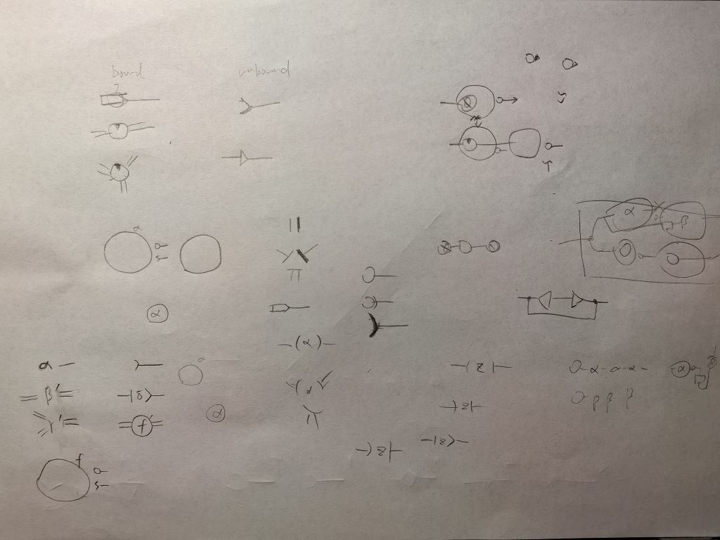
Primitives
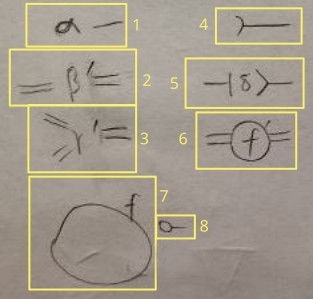
- 1. terminal
Terminals are compared by name. This fact is important in reduction.
You can think of it as “literal”.
- 2. 2-sided one-to-one relation
All relations are compared by name.
A one-to-one relation has >=2 sides. Each side has >=1 connections.
It is similar to injective function.
The “tick” on the upper right of the name is not part of the name. It represents the orientation (rotational placement) of the primitive. This is the only way to tell which connection is which, since one can draw primitives in every orientation.
- 3. 3-sided one-to-one relation
This is a 3-sided variant.
- 4. handle
Prevents connected components from being erased. Also how you get the result of a computation.
- 5. many-to-one relation
It is similar to regular function.
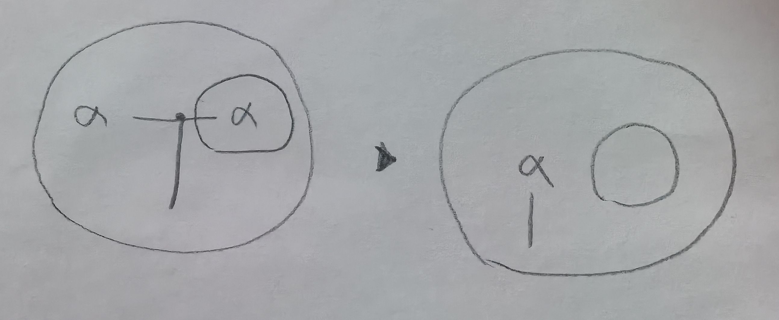
- 6. use region
Insert a region when needed (lazy).
- 7. define region
Define a region. The name is optional.
A region may be contained in another region, but never partially overlap with another region.
- 8. insert if empty
If a region becomes empty (no primitives inside), another region is inserted into the network.
Terms
Each primitive have ports where you can draw lines from. This is for visual representation only.
The ports in a network are grouped into connected components. Each component is what you would call in type theory “term”.
One consequence of this is that a network is not a graph, as there are no clear vertex and edge types.
In drawn notation, you will see intersections that look like the ones in electrical wiring diagrams. You can think of it as a fully connected component in a graph. However, a network of this kind is not a graph. You will get used to it.
Reduction rules
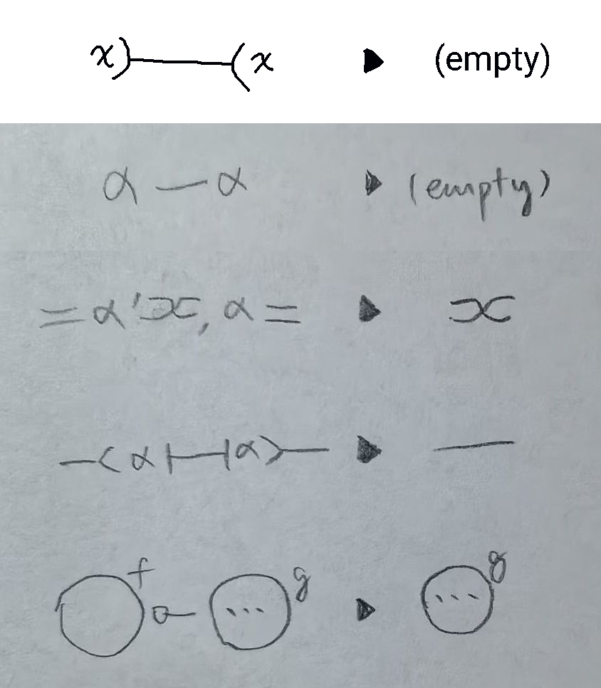
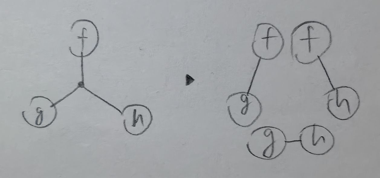
For one-way relations (third rule from the top), if any one side match, all other sides are linked together.
In the last rule, when region f is not empty, primitives inside region g cannot participate in reduction.
When merging two primitives, the new primitive is placed inside the nearest common anscestor of the two regions (each primitive has a containing region). There is an implicit global region.
There is also this rule for spliting the graph for parallel processing. It makes the theory of reduction simpler. In practice though, it might be too expensive for a compiler.
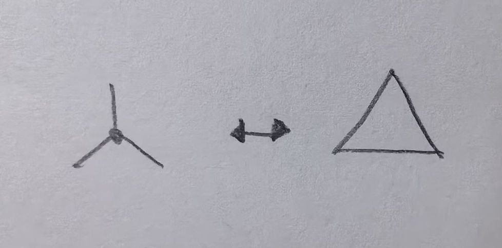
What about many-to-many relations
They are kind of useless since they can’t reduce. So, they are not included.
You can do this with one-to-one relation though:

Uses
This system is a general framework of computation.
While this system is more complex than interaction nets, I hope it is easier to use for people who are familiar with relational algebra, relational logic or lambda calculus.
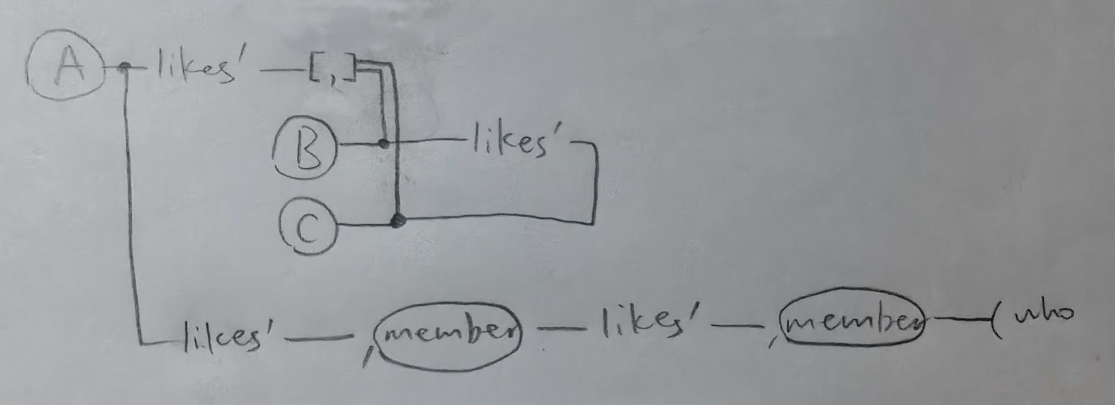
Use it as a graph database with query
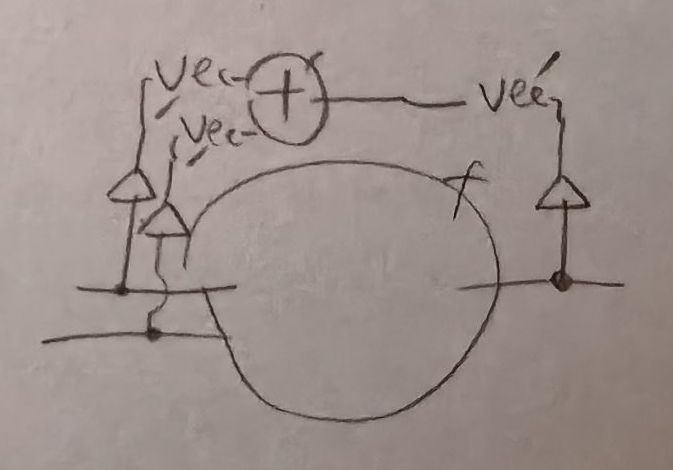
f: Vec m -> Vec n -> Vec (m + n)
I’m sure you can think of more uses.
How to name this mathematical system
I don’t really know.
Some ideas:
- relation nets (in homage to interaction nets)
- relational network
- relational wiring
- relational wiring diagram
- relational wiring notation (for the graphical notation)
If you have a better idea, please tell me.